Wire bonding for EV batteries and inverters:
Published online in “Charged – Electric Vehicles Magazine“; Issue June 2017
Author: Mike McKeown, Sr. Business Development Manager at Hesse Mechatronics
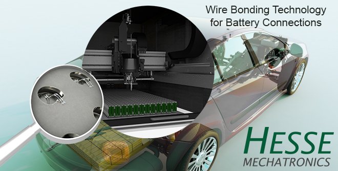
All electronic devices need to be connected electrically (and mechanically) and there are numerous ways of completing this task. Wire bonding is one type of interconnection. There are three types of wire bonding: thermocompression, thermosonic and ultrasonic. We will focus on ultrasonic wedge bonding with aluminium wire and discuss the wire bonding process and how to connect to various materials involved with battery systems, inverters and converters.
What is Wire Bonding?
A wire bond is the joining of a wire onto a surface that results in an atomic interaction. Normally the wire will have 2 bonds (1st and 2nd bonds) with a loop in between. You could have multiple bonds in between the first and last bonds, and this could easily be done via the wedge bonding process (it is more time consuming when done with ball bonding).
Aluminum wire is situated beneath a bond tool and brought to the surface at a constant velocity. Once touchdown has been verified, ultrasonic power is applied for a period of time (in milli seconds) with an applied force. A frequency of 60 kilo Hertz (kHz), or 60,000 cycles per second, is commonly used for aluminum wedge bonding. The vibration of the bond tool softens the wire and the surface, and, as they come into contact, they share each other’s electrons. Once the bonding time is done, the wire and surface have bonded together. No heat is generated during this process. No post-cleaning is required after the bond has been made.
Quality Criteria for Wire Bonds
Once wire bonds are completed, they are subjected to various types of tests. The most commonly used tests are destructive and they are the pull test and the bond shear test. For electrical testing, the “Leakage Test” is quite relevant.
For the destructive pull test, a hook is placed mid-span between the two bonds and pulled until the wire breaks. The optimum scenario is that the wire breaks mid-span. Second-best scenario is the wire breaking at either bond. It is not desired to have “lifts”, where the entire bond wire lifts away from the surface. The main reasons for doing a destructive pull test is to check for adhesion, heel strength, loop height, correct wire diameter and contamination detection. One general rule that many in the microelectronics industry use is that the minimum wire break should be at least half the tensile strength of the bond wire you are using.
For bond shear testing, this test is for wire diameters larger than 100 microns (4 mils). The basic concept is that a shear tool pushes the bond from the side until it removes it from the surface. The force is evaluated as well as the remnant. A general rule-of-thumb is the minimum bond shear force is the tensile strength of the wire and at least 25% remnant, but >50% is preferred.
The shear test’s main goal is to measure adhesion of the wire onto the surface. Other items that the bond shear test is useful for is detecting contamination and die cratering.
For the Electrical Test, the main item to evaluate with wire bonds is the Insulated Gate Leakage Current Test. This is only applicable when wire bonding onto die (e.g. IGBT, SiC, MOSFET, etc.). If the bond force is too low during the bonding process, this could cause micro-cracks to form and damage the die structure. If a failure occurs, you would want to set your force parameter to be close to the tensile strength of the wire being used. The Visual Test is one that is commonly overlooked or not utilized fully. Below is a photo showing acceptable wire bonds.
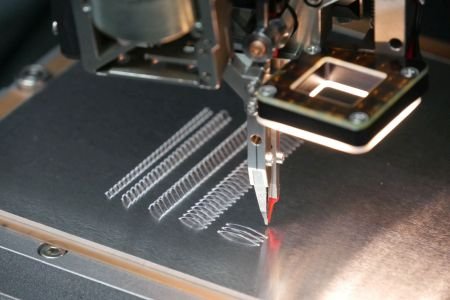
Wire Bonding with Heavy Wire Bondhead of Hesse
All you need is a microscope with 10X to 20X optics. The key item is to have the proper documentation and photos as to what constitutes a good and a bad wire bond. The Visual Test is an excellent method to measure: bond location, bond tail length, bond deformation, loop height, and very importantly – heel cracks.
Once a wire bond process has been developed and you have your process window developed, Reliability Tests are done on the modules or system. These tests may include: Thermal Cycling, Thermal Shock, Vibration, Autoclave, 85/85, etc. These tests are normally defined by the industry that the wire bonds will be involved in. The purpose of these Reliability Tests is to check: bond adhesion, heel cracks, contamination, micro-cracked die, and excessive intermetallics.
Bonding Surfaces for Batteries & Inverters
For the batteries, the most common wire bondable surfaces are electrolytic nickel, aluminum and ENIG or ENEPIG. ENIG is an industry acronym that stands for Electroless Nickel Immersion Gold and ENEPIG is Electroless Nickel Electroless Palladium Immersion Gold. They are the most commonly used wire bonding surfaces for PCBs (printed circuit boards). Refer to the IPC Standards: IPC-4552 Specification for Electroless Nickel Immersion Gold (ENIG) Plating for Printed Circuit Boards and IPC-4556 Specification for Electroless Nickel/Electroless Palladium/Immersion Gold (ENEPIG) Plating for Printed Circuit Boards.
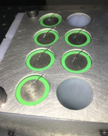
Al wire on 18650 and Al Collector plate.
The aluminum (Al) for collector plates and busbars is usually of the 3000 Series. For cylindrical cells, like 18650 or 21700, the bondable surface is typically electrolytic nickel.
For prismatic applications, wire bonding is a common connection method for Voltage Sense. This is usually from a busbar onto a PCB. The busbar metallization is typically 3003 Al and the PCB is ENIG or ENEPIG.
Ribbon versus Round Wire Bonding
Round wire is commonly used for cylindrical cells, but for prismatic cells, ribbon bonding could be more beneficial. Aluminum ribbon bonding is more of a robust process not just for current capability but also for mechanical stability and thermal conductivity. The Al ribbon would be a much stronger interconnection method when bonding from the prismatic cell onto the busbar. If there is an aluminum tab connection to be made to the busbar, the wire bonder could be utilized as an ultrasonic interconnection machine, which doesn’t have wire or ribbon beneath the bond tool – it ultrasonically attaches the two metals together.
Below is a chart showing approximately how many single ribbons would replace multiple round wires for a given wire diameter.
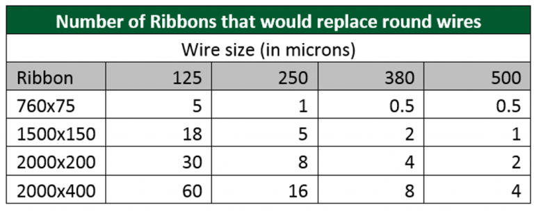
Number of Ribbons that replace round wires
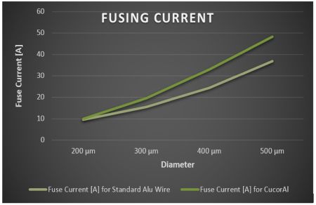
Chart : Loop Length: 20 mm; Ramp: 0.2 A/s (courtesy of Heraeus)
One 500µm wire ~35A fusing current. One 2000µm x 300µm ribbon replaces 3 x 500µm wires (~105A fusing current with one 2000µm x 300µm ribbon)
Process integrated Quality Control
Hesse Mechatronics developed and patented a bond quality monitoring program that is unlike any other system for any form of interconnection (welding, soldering or
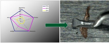
Detected Particles Found Using PiQC
other wire bonders). The PiQC calculates a Quality Index for each bond based upon real-time feedback signals. If the bond does not meet or exceed the quality threshold, you could set up the wire bonder to do a non-destructive pull test on that particular bond, stop the machine or flag that part for further evaluation. It measures up to five variables: mechanical oscillation of the bond tool, friction at the bond surface, transducer current, ultrasonic frequency and bond deformation. Data is stored in files that are easily accessible for future reference.
Conclusion
Wire bonding has been utilized in various types of batteries and inverters (as well as DC-DC Converters) for many years. Wire bonding has been a proven interconnection method in the military, aerospace, automotive, medical, RF/Microwave, consumer, power and many other markets since the 1960’s. Ribbon bonding could be utilized when a more sturdier interconnection is required to handle vibration, current or thermal situations. With PiQC, you now have a wire bond system that is constantly monitoring the bonding process and alerting you when something is changing – in real-time, with no penalty to your production throughput.
Lesen Sie den Artikel online auf ChargedEV .
Für mehr Informationen:
Hesse GmbH, Lise-Meitner-Str. 5, D-33104 Paderborn
T: +49 52 51-15 60-0
E-Mail: sales@hesse-mechatronics.com
